Electric Circuits Legacy Problem #25 Guided Solution
Problem*
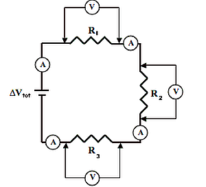
Voltmeters can be used to determine the voltage across two points on a circuit. An ammeter can be used to determine the current at any given location on a circuit. The circuit at the right is powered by a 60.0-volt power source and utilizes three voltmeters and three ammeters to measure voltage drops and currents. The resistor values are 10.3 Ω (R1), 15.2 Ω (R2) and 12.8 Ω (R3). Determine the ammeter readings and voltmeter readings.
Audio Guided Solution
If you've done electricity labs in your physics class, it's quite likely that you've used ammeters and voltmeters. These are devices which are used to measure the current in the voltage drop between two points. The ammeters in this diagram are represented by the symbol A, and they're simply wired in series in the series circuit, and they measure the current at whatever location you place it. The voltmeters, when used in lab, usually consist of two probes, which you click on metal components on the circuit, maybe on one side of the resistor and on the other side, and as such they find the electric potential difference between the two points that you tap on when you tap on the metal parts of the circuit. Here these are represented by the V with a circle around them in the diagram, and they're measuring the electric potential difference, or voltage drop, across the three resistors. In a series circuit, the total resistance is simply the sum of the individual resistance values of the three resistors in the circuit. So as we solve this problem, that's the place we're going to begin. We're going to take the 10.3, 15.2, and 12.8 ohms, and we're going to add them together and find the total resistance. It's not something that they particularly ask for, but it will be strategic in our task of trying to find the current ammeter readings and the voltmeter readings. So when I do that, I end up getting 38.3 ohms as the total, or equivalent, resistance, and the current through the battery is just going to be the battery voltage divided by this total resistance. When I take the 60.0 volt battery voltage and divide 38.3 into it, using the equation I equal delta V over R, I get 1.566 repeating amperes as the current through the battery. Though in a series circuit, that current is everywhere the same. It's the same in the battery as it is in the first resistor, as it is in the second and the third, etc. And so all the ammeter readings will read 1.566 repeating, though it would be probably to two decimal places as 1.57 amperes. Now to find the voltage drop, I can use the same equation, delta V equal I R. But when I use it, I'll have to use the right resistance value to calculate the proper delta V. For instance, for the voltmeter probe that touches on one side and the other side of the R1 resistor, I'll have to use R1's resistance value to calculate the voltage drop between those two points. So I go delta V equal I R, and for I I use 1.56 repeating, and for R I use 10.3. I get 16.1358, and that's the voltage drop across this resistor, since that's the resistance and the current between those two points. Now for R2, of course, I'm going to use the same equation, only I'm going to go I of 1.566 multiplied by 15.2 ohms for R2. I'll end up getting 23.8120 as the voltage drop across the two points being touched on opposite sides of the R2 resistor. I can round that to three significant figures as well, 23.8. Finally, for R3, I do the same thing, using as my R3 value 12.8 ohms, and I get 20.0522. I can round that to three significant digits, such that it's 20.1 volts. One thing you'll notice, that if you take these three voltage drops for going around the circuit through the three different resistors, they sum up to the 60.0 voltage gained as a charge passes through the battery. That's what we should expect.
Solution
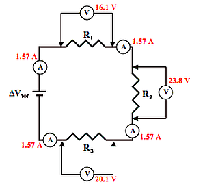
Ammeter readings: 1.57 A (for each)
Top voltmeter reading (across R1): 16.1 V
Right voltmeter reading (across R2): 23.8 V
Bottom voltmeter reading (across R3): 20.1 V
Habbits of an Effective Problem Solver
- Read the problem carefully and develop a mental picture of the physical situation. If necessary, sketch a simple diagram of the physical situation to help you visualize it.
- Identify the known and unknown quantities and record them in an organized manner. Equate given values to the symbols used to represent the corresponding quantity - e.g., \(\descriptive{\text{δV}}{δV,change in voltage} = 9.0\unit{\volt}\); \(\descriptive{R}{R,resistance} = 0.025\unit{\ohm}\); \(\descriptive{I}{I,current} = \colorbox{gray}{Unknown}\).
- Use physics formulas and conceptual reasoning to plot a strategy for solving for the unknown quantity.
- Identify the appropriate formula(s) to use.
- Perform substitutions and algebraic manipulations in order to solve for the unknown quantity.
Read About It!
Get more information on the topic of Electric Circuits at The Physics Classroom Tutorial.