Electric Circuits Legacy Problem #32 Guided Solution
Problem*
Voltmeters can be used to determine the voltage across two points on a circuit. An ammeter can be used to determine the current at any given location on a circuit. The circuit below is powered by a 24.0-volt power source and utilizes four voltmeters and three ammeters to measure voltage drops and currents.
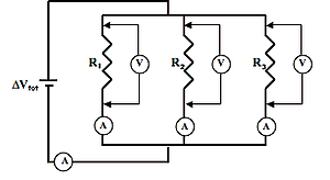
The resistor values are 54.5 Ω (R1), 31.7 Ω (R2) and 48.2 Ω (R3). Determine the ammeter readings and voltmeter readings.
Audio Guided Solution
Now if you�ve done many electric circuit labs in your physics class, you�d likely use voltmeters and ammeters, or simply multimeters. Ammeters are devices which measure current and they�re just simply wired within a circuit at a given location to measure the current at that location. Voltmeters on the other hand are more mobile in the sense that they�re not wired into a circuit and they can be moved from one part of a circuit to another. They simply have two probes coming out of them and they�re tapped on metal components of the circuit at two different locations in order to measure the electric potential difference across those two locations. In this case, what we�re doing is using a voltage meter or voltmeter in order to measure the voltage drop across the resistors within a parallel circuit. Now in order to successfully approach a problem like this, you need to have a good conceptual understanding of what�s going on in a parallel circuit. And here�s what�s going on. You have the collection of charges which are leaving the battery and traversing through the wires. They come to a point on the circuit known as a node and it�s at that point that the charges make a choice as to which one of the three resistors they will pass through. They won�t go through all three resistors. They�ll simply go through one of the resistors, not each one through the same, but each one through likely a different resistor and then they will come back together at another node and then travel back to the negative terminal of the battery. And so we describe parallel circuits as having branches and branching locations where the charge branches off into separate resistors. Now what�s true about those resistors or those branches is that the charge will lose voltage within them and the voltage drop that they will lose is equal to the voltage they gain within the battery. Now since a charge isn�t going through all three resistors but rather simply one of the resistors, it�s only going to have a voltage drop of 24 volts, equal to the voltage gain within the battery. And so what we ought to notice when we tap and tap across any of the resistors is we ought to notice a voltage drop of around 24 volts. In reality there�s a little bit of resistance in every wire which gives you a little bit of a voltage drop when traveling through the wires. So we might expect that for a true 24 volt battery, 24 volt power source that we have just a little bit less than 24 volts. What we could list it here is 24 volts voltage drop. Now in order to find the current within each of the individual branches, what we need to do is use the equation delta V equal IR. Knowing that the delta V for any of the branches is 24 volts and knowing the R values we could calculate the I values. When applied to the first resistor on the left, R1, we would say that I1 is equal to delta V1 of 24 volts divided by the R1 value of 54.5 ohms. When doing so we would get an I1 value of 0.4404 amps. We could repeat the process for resistor 2, saying that I2 is equal to delta V2 of 24 volts divided by the R2 of 31.7 ohms. We would get 0.7571 amps as our current through that second or middle resistor. Now for resistor 3 we do exactly the same thing, say I3 is equal to 24.0 volts divided by 48.2 ohms and we end up getting 0.4979 amps. Those are the answers to what the ammeters would read. So the final thing that we could do is figure out what the ammeter would read outside of the branches. That is in the very bottom part of the circuit. Now you will recall I mentioned that charge divides up and passes through the branches and then comes back together again in such a manner that the total current outside of the branches is equal to the sum of the currents within the branches. So that current outside of the branch ought to read the sum of I1 plus I2 plus I3, which we have already calculated. When you sum up all those currents you end up getting about 1.695 amps as the current outside of the branches. And that is what that bottom ammeter would read. Now of course I will give you another way to approach some of these problems and one of them is to use your equation that the equivalent resistance is simply the sum of the reciprocals of the individual resistances. I think I said that wrong. Let me tell you the equation. It is 1 over R equivalent is equal to 1 over R1 plus 1 over R2 plus 1 over R3. And so what we need to do is substitute our R1, R2, R3 values into the equation and evaluate the right side of it. When you evaluate the right side by taking the sum of the reciprocals you get 0.07064. Now that is not the equivalent resistance. That is 1 over the equivalent resistance. So to find the equivalent resistance you simply take the reciprocals of each side of the equation and when you do you get 14.156 ohms. Now to find the total current outside the branches you simply say the delta B total equals the I total times the 14.156 ohms. When you do that you also get 1.6954 amps. Now in this discussion I hope you have seen that as evident. That is a clear conceptual understanding of what is going on in a circuit really facilitates the solution of these problems.
Solution
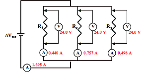
Left ammeter reading (in R1 branch): 0.440 A
Middle ammeter reading (in R2 branch): 0.757 A
Right ammeter reading (in R3 branch): 0.498 A
Bottom ammeter reading (outside branches): 1.695 A
Voltmeter readings: 24.0 V (for each)
Habbits of an Effective Problem Solver
- Read the problem carefully and develop a mental picture of the physical situation. If necessary, sketch a simple diagram of the physical situation to help you visualize it.
- Identify the known and unknown quantities and record them in an organized manner. Equate given values to the symbols used to represent the corresponding quantity - e.g., \(\descriptive{\text{δV}}{δV,change in voltage} = 9.0\unit{\volt}\); \(\descriptive{R}{R,resistance} = 0.025\unit{\ohm}\); \(\descriptive{I}{I,current} = \colorbox{gray}{Unknown}\).
- Use physics formulas and conceptual reasoning to plot a strategy for solving for the unknown quantity.
- Identify the appropriate formula(s) to use.
- Perform substitutions and algebraic manipulations in order to solve for the unknown quantity.
Read About It!
Get more information on the topic of Electric Circuits at The Physics Classroom Tutorial.